1. Air end/motor system:
Single-screw air compressor is also called worm air compressor. The meshing pair of single-screw air compressor consists of
a 6-head screw and two 11-tooth star wheels. When the worm meshes with two star wheels at the same time, the force on the
worm is balanced and the displacement is doubled. The screw compressor we usually refer to generally refers to a twin-screw
compressor.

A screw (twin-screw) compressor has a pair of intermeshing, oppositely rotating helical toothed rotors. The rotor with convex tooth
surfaces is called a male rotor, and the rotor with concave tooth surfaces is called a female rotor. As the rotor rotates in the body,
the working volume changes continuously due to the intrusion or disengagement of the teeth, thereby periodically changing the
volume between each pair of tooth slots of the rotor to achieve the purpose of suction, compression and exhaust.

The main engine is the core component of the screw machine. The structure and working mechanism of the main machine of any
brand of screw machine are similar.

(1) Inhalation process
When the rotor rotates, a tooth of the male rotor continuously separates from a tooth groove of the female rotor, and the volume between
the teeth gradually expands and is connected to the suction orifice. The gas enters the volume between the teeth through the suction
orifice until the volume between the teeth reaches the maximum. When the value is reached, it is disconnected from the suction orifice,
and the teeth and the inner shell work together to close the volume between the teeth, and the suction process ends. It is worth noting
that at this time, the inter-tooth volumes of the male rotor and the female rotor are not connected to each other.
(2)Compression process
The rotor continues to rotate. Before the volumes between the teeth of the female and male rotors are connected, the gas in the volume
between the teeth of the male rotor is compressed by the invasion of the teeth of the female rotor. After passing a certain corner, the volumes
between the teeth of the female and male rotors are connected, forming a " The V"-shaped inter-tooth volume pair (primitive volume), as the
two rotor teeth squeeze into each other, the primitive volume is gradually moved, and the volume is gradually reduced, realizing the gas
compression process. The compression process is carried out until the volume of the element is connected with the exhaust orifice.
(3)Exhaust process
As the volume of the element continues to shrink when the rotor rotates, the compressed gas is sent to the exhaust pipe, and this process
continues until the volume is minimum.
With the continuous rotation of the rotor, the above-mentioned suction, compression, and exhaust processes are carried out cyclically, and
the volumes of each primitive work in sequence, forming the working cycle of the screw refrigeration compressor.
From the analysis of the above process, it can be seen that when the two rotors turn to the side that caters to each other, that is, the side
where the convex teeth and the concave teeth cater to each other, the gas is compressed and forms a higher pressure, which is called a
high pressure zone; on the contrary, the screws turn to each other. On the deviating side, that is, the side where the convex teeth and the
concave teeth are separated from each other, the volume between the teeth is expanding to form a lower pressure, which is called a low
pressure zone. These two areas are separated by the contact line between the casing and the rotor. It can be roughly considered that the
axial plane of the two rotors is the interface between the high and low pressure areas. In addition, the spiral channel formed by the meshing
line between the male and female rotors causes the gas in the unit volume to spirally move from the suction end to the exhaust end while
being compressed.
As a type of rotary compressor, the screw compressor has the characteristics of a centrifugal compressor in terms of structure, and it belongs
to the category of positive displacement compressors in terms of working principle.
Disadvantages:
1. The spatial curved surface of the spiral rotor requires high machining accuracy;
2. The meshing lines between the rotors cannot achieve good inter-stage sealing and due to limitations of the rotor stiffness, the current screw
compressor cannot achieve higher performance. End pressure;
3. The medium periodically passes through the suction and exhaust orifices at high speed, and leakage through gaps and other reasons make
the compressor noisy, and noise reduction measures need to be taken;
4. Due to the above characteristics, screw compressors are generally used Under the following working conditions:
1. The flow rate is not very high
2. It needs to run smoothly for a long period
3. The exhaust pressure is not high
Chassis:
It consists of the body, suction end seat and exhaust end seat, and is the main component of the compressor. The machine body is the central
component that connects various components. It provides the correct assembly position for each component to ensure that the female and male
rotors mesh in the cylinder and work reliably. The shape of its end face is ∞, which is compatible with the outer cylindrical surfaces of the two
meshing rotors, allowing the rotors to be accurately installed into the body. The inner wall of the body is provided with radial suction holes that meet
the requirements of the rotor angle to ensure the smooth suction process of the rotor during rotation.
The suction and exhaust end seats are sealed connections located at the front and rear ends of the machine body. In addition to serving as end face
seals of the machine body, more importantly, they provide assembly positions for the female and male rotors and the bearings that support the rotors.
Rotor:
The main components that realize variable volume compression are composed of female and male rotors. The rotor tooth shape is processed with
high-precision special machine tools and special cutting tools, and is one of the key parts of the compressor. The rotor profile is often a unilateral
asymmetric cycloid - arc profile. There are two structural ways of Yin and Yang rotors:
1. The male rotor is connected to the motor as the active rotor, transmits torque, and at the same time drives the female rotor (driven rotor) to rotate
through the meshing relationship.
2. The female and male rotors mesh with the driving gear driven by the motor through their respective driven gears to transmit torque.
Bearings:
The bearing is a part that supports the female and male rotors and ensures the high-speed rotation of the rotors. The motor end generally uses roller
bearings for support. Secondly, when the rotor rotates and compresses the gas, it will generate axial thrust. In order to overcome this axial force, the
other end of the rotor uses a tilted column bearing, which not only overcomes the axial force of the rotor rotation, but also bears the radial force.
Most screw compressors adopt oil injection lubrication. The lubricating oil is mixed with the fuel and enters the compressor, and the machine is lubricated
and sealed with the flow of the medium. Its advantages are as follows:
1. Reduce exhaust temperature.
2. Reduce working fluid leakage and improve sealing effect.
3. Enhance the lubrication of parts and extend the life of parts.
4. It has absorption and damping effects on sound waves and can reduce noise.
5. Rinse away mechanical impurities and reduce wear. However, due to the large amount of oil injection, a lubricating oil system must be added, and an oil
and gas separator must be added at the compressor outlet, which will increase the size and complexity of the unit. At the same time, this method cannot be
used for media that do not allow pollution. Therefore, there are also some screw compressors that have no
oil lubrication.
Compressors that use oil-free lubrication have higher requirements on the meshing clearance of the male and female rotors, the stiffness and quality of the
rotors, and the processing quality of the entire unit.
Motor system:
The connection between the host and the motor——rigid transmission method——gear

2. Cooling/separation system:
The cooling system is one of the very important parts of the air compressor, because the air releases a large amount of heat after being compressed,
and this heat must be taken away by the cooling system for heat exchange. Cooling systems are divided into two categories: air-cooled and water-cooled.
(1) Air-cooled cooling system
The air-cooled cooling system consists of two major components: a fan and a cooler. The cooler uses an aluminum plate-fin heat exchanger. The fan
forces cold air to the cooler. When the air flows through the cooling fins of the cooler, it mixes with the compressed air. Or the lubricating oil performs
heat exchange to take away the heat to achieve the effect of cooling the compressed air and cooling the lubricating oil.
Things to note when using air-cooled units:
1. The temperature of the cold air (basically equal to the ambient temperature) is very important and cannot be too high. It is recommended not to exceed 40°C.
2. When the cooler is exposed to the air, the fins will be stained with dust. If too much dust accumulates, it will seriously affect the heat exchange effect of the
cooler. Therefore, compressed air should be used frequently to blow away the dust on the surface of the fins. If the situation is serious and cannot be blown clean,
it must be cleaned with detergent.
When cleaning the unit parts, it is strictly prohibited to use flammable, explosive, and volatile cleaning agents. When cleaning, you can remove the cover on the
side of the cooler bracket and use a hand-held air gun to blow upward.
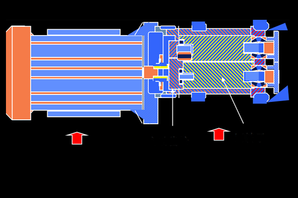
(2) The water-cooled cooling system uses a shell-and-tube cooler.
One is a rear cooler used to cool the compressed air, and the other is an oil cooler used to cool the lubricating oil before it is sprayed into the body. This kind of
cooler has many thin-walled heat exchange copper tubes arranged in parallel in the tube shell. The water flows inside the copper tube, and the hot oil or hot air
flows outside the copper tube. After heat exchange, the water takes away the heat of the oil and air. .
Water-cooled coolers are less sensitive to ambient temperature conditions and are easier to control the exhaust gas temperature. However, if the quality of the
cooling water is too poor, the cooler will easily become blocked or corroded, leading to increased maintenance costs. It may even cause serious damage to the
cooler and cause it to be scrapped. It is recommended that cooling water should at least meet the following requirements:
Water pressure: ≥0.2MPa, ≤0.5MPa, inlet water temperature ≤32 oC, water volume varies according to different models.
In areas with hard water, water softeners must be added to the circulating water and the water must be changed regularly. If there are too many impurities in the
water, a water filter must be installed on the cooling water inlet pipeline of the air compressor.
Water-cooled units will also be equipped with a small fan for heat dissipation within the chassis.
The cooling system includes an air cooler (after cooler) and an oil cooler (front cooler), both of which are cooled by fans on the motor.
Aftercooler features:
1. Cool the compressed air leaving the unit.
2. Allow up to 70% of the water content to condense out.


Air-cooled cooling system:
The cooling system includes an air cooler and an oil cooler, both of which are cooled by fans on the motor. The oil cooler is a front cooler for cooling oil and an after
cooler for cooling compressed air. There is an oil injection system installed. When the oil temperature is lower than 40℃, the oil directly enters the body without going
through the cooler. When the oil temperature exceeds 55°C, the valve closes to allow all the oil to be cooled through the oil cooler before entering the main engine.

Thermostatic valve:


Oil filter:

Micron grade protection main engine bearings keep the system clean. Function: Prevent foreign matter from entering the main engine and increase coolant life.
Oil cut off solenoid valve:

Oil separation system:
1. Separate compressed air from lubricating oil
2. Make sure the lubricant remains in the system.
3. Reduce the oil content in the user's air duct.

Effect:
1. Store coolant.
2. Primary separation.
composition:
1. Separation cylinder
2. Oil separation core (replaced once every 2 years)
3. Oil return pipe
4. Minimum pressure valve
3. Air path adjustment system:

Minimum pressure valve:
1. Set to open at 4.0 Bar (4.2kg)
2. Prevent the separator from being impacted by low pressure and maintain its pressure
3. Helps separate systems
4. Prevent pipe network pressure from entering the cooling system when the unit is unloaded or shut down.


4. Control circuit system: intake butterfly valve
effect: Control air intake.

Protection System:
1. Host high temperature protection---temperature switch
2. Overcurrent protection---------main motor thermal relay 1OL
3. Fan motor thermal relay 2OL (M37)
4. Pressure vessel protection----safety valve
Temperature Switches:
1. M250 main engine exhaust temperature switch (1ATS)---119 °C2. M250 main engine bearing temperature switch (5TS)-----109 °C.
maintenance:
1. Replace the oil filter element on time: 150 hours for the first time, and up to 2000 hours thereafter.
2. Replace the coolant on time: super cooling can last up to 8,000 hours or two years.